Uber Shader
Shader Overview
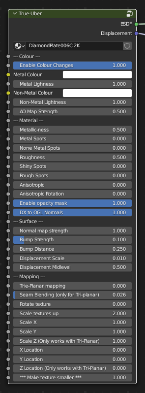
The True-Uber shader is designed for use with texture sets centered around Metallic and materials that don't fall into Organic, or Plastic materials. The ideal use for this material option would be for texture sets like raw/painted metals, rocks, grounds, hard surfaces like concrete or marble.
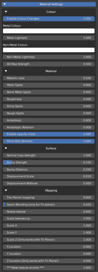
The shader is broken up into 4 distinct sections, in the UI using drop-down functions. This is to make the UI cleaner and allow the user to close information that is not needed. If you view this in the shader-editor, or the material properties, it will not look like the image on the left but will look like this:
We advise using only the options in the UI for convenience. However if you edit the node-group and change any input names, this will break the functions in the UI.
Shader Breakdown
Colour
Enable Colour Changes: This is a 0-1 slider value that will allow for adjustment directly to the HUE's on the diffuse/albedo map. This will not affect maps that are in the greyscale and will have limited effect on dark or very light hues.
Metal Colour: This is a colour picker value. Click this and choose a new colour from the colour wheel. This will only adjust the hue of the material based on the METALLIC map values. This means it'll only affect the metal parts of a material.
Metal Lightness: This is used to make the metal colour lighter or darker. Ranges from 0-2 and default at 1
Non-Metal Colour: This is a colour picker value. Click this and choose a new colour from the colour wheel. This will only adjust the hue of the material based on the NON-METALLIC map values. This means it'll only affect the metal parts of a material.
Non-Metal Lightness: This is used to make the metal colour lighter or darker. Ranges from 0-2 and default at 1
AO Map Strength: This will affect the intensity of an AO map if detected.
Explanatory GIF
Two texture types to show how different settings affect textures using Uber-Shader (Drivers are not enabled by default. This has been done for demo purposes)
Material
Metallic-ness: This will adjust the metal values in the shader. If there are "metal" areas, then you can make these non-metal by setting the value to 0. If you wish to make non-metallic materials more metallic, then set this between 0.5 and 1
Metal Spots: This will attempt to change how the metallic map effects the shader. If the map has enough range in it, then this value will show more visible metal areas. This may be best seen when roughness or rough/shiny spot values have been adjusted. If the Metallic map is a pure black and white map with no range between those values, then this will not work.
Non Metal spots: This will do the same as the above value, but for the non-metal masked sections of the metallic map.
Roughness: This will affect the roughness of the shader based on the roughness map that was applied. This ranges from 0-1 and 0.5 being default (which is the roughness map with no changes applied) Lower values make it glossier, and higher values make it rougher.
Shiny Spots: This affects the black-clip of the roughness map. Higher values will make the black-levels of the map more obvious, creating patches of higher gloss areas. Higher values may make the whole map dark, which in turn makes it glossier. This is a 0-1 value.
Rough spots: This affects the white-clip of the roughness map. Higher values will make the white-levels of the map more obvious, creating patches of higher rough areas. Higher values may make the whole map light, which in turn makes it rougher. This is a 0-1 value.
Anisotropic: This will enable the Anisotropy Value in the shader. See more information HERE
Enable Opacity masks: This is on by default and will make sure any materials that have an alpha mask come in with that mask enabled, allowing for transparent sections.
DX to OGL Normals: This value is a 0-1 value, and is set to 0 by default. This will flip the Green channel of a normal map so that it converts normal maps from Direct X (DX) to OpenGL (OGL) or vice-versa. This should be used if your shadows look wrong or if you know exactly what format the Normal map is in.
Explanatory GIF
Surface
Normal map strength: This will affect the intensity of the normal map. 1 is default, and ranges from 0-10. Values can be keyed-in outside of this range, but beware this may provide unwanted results.
Bump Strength: This will affect the bump/height map value. This is a 0-1 value.
Bump Distance: This changes the perceived height of the bump map. The correct way to use a bump map is to set the strength to 1 and then adjust the intensity with this value. Values equate to Blender units (or whatever you have set units to) for example 0.25 in here would be equivalent to 2.5cm in height. This value is limited to 5 but any value can be keyed in. If you wish to invert the bump, set negative numbers.
Displacement Scale: This is the strength of the displacement map. The height of the displacement intensity is the same as the bump in that a value of 0.25 will equate to a 2.5cm displacement value.
Displacement Midlevel: This offsets the location at which the displacement will start from. Higher values will make the displaced mesh move inward from it's original volume, lower values will make it move outward from it's original volume.
Displacement usage
Displacement of the mesh will ONLY work if you have set the "experimental" feature set in the render properties. It is CYCLES ONLY, and there needs to be a subsurface modifier on the object set to "adaptive" otherwise this will not work as shown in the GIF
Explanatory GIF
Mapping
Tri-Planar mapping: This will swap from a UV map, to a projected procedural mapping system that maps directly to the XY and Z coordinated of a mesh. This is useful for removing stretching of textures on objects with high-sloping faces.
Seam Blending (only tri-planar mapping): This will blur the visible seams from the Tri-Planar mapping system. This can cause artefacts when using adaptive displacement
Rotate texture: This rotates textures along their mapped co-ordinates. The values in here should be treated as rotation in degrees. 90, would be a rotation of 90 degrees.
Scale textures up: This scales the textures to look larger.
Scale X: This will scale textures along the X axis. Higher values mean there will be more repetitions in the texture.
Scale Y: This will scale textures along the Y axis. Higher values mean there will be more repetitions in the texture.
Scale Z: This will scale textures along the Z axis. This only works when Tri-Planar mapping is enabled as UV maps do not have a Z axiz. They only work along XY (UV). Higher values mean there will be more repetitions in the texture.
X Location: This will move the mapped texture along the X axis
Y Location: This will move the mapped texture along the Y axis
Z Location: This will move the mapped texture along the Z axis. This only works with Tri-Planar mapping enabled as a UV map does not have a Z axis.
Make Texture Smaller: Increasing this value will increase the AMOUNT of tiles generated. This makes the texture appear smaller as it's scales down to add more tiles in the same mapping coordinates. This affects all previous mapping settings.
Explanatory GIF