
Simulations
Nodes that run an algorithm as many times as the user sets.
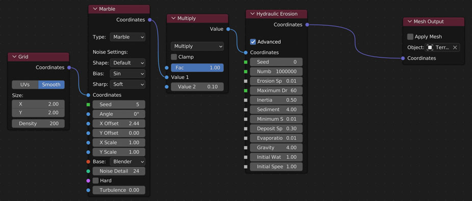
Hydraulic Erosion
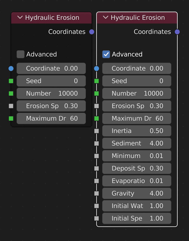
Simulates the effects of rain on terrain.
- Randomize the location of all the rain drops. Is NOT consistent.
- Number of raindrops to simulate. Higher values increase simulation time
- Affects how much sediment to erode (remove) from terrain
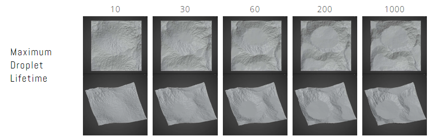
- The maximum amount of time (iterations) the droplet has to complete its travel throughout the terrain. Higher values allow for more droplets to complete their paths, though the default value typically is enough. Higher values increase simulation time
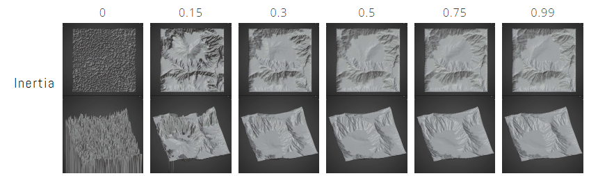
- Inertia
- The amount of inertia each drop starts with. Smaller values result in deeper grooves
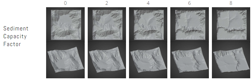
- Sediment Capacity Factor
- Maximum amount of sediment each droplet can carry at a given time. Higher the faster the droplet is going. When capacity is met, droplet deposits sediment (adds a bit to the terrain)
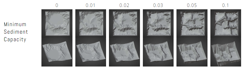
- Minimum Sediment Capacity
- Amount of sediment the droplet will always carry
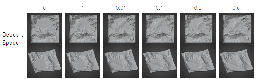
- Deposit Speed
- Affects how much sediment to deposit (add) to terrain
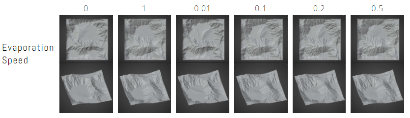
- Evaporation Speed
- Affects the lifetime of the droplet. Higher values reduce lifetime quicker
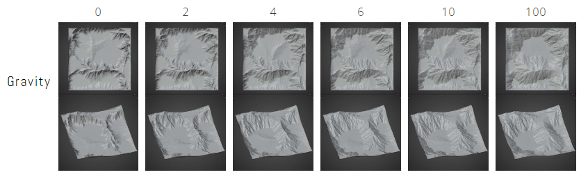
- Gravity
- Affects the speed of the water droplet.
- Initial Water Volume
- Initial size of each droplet
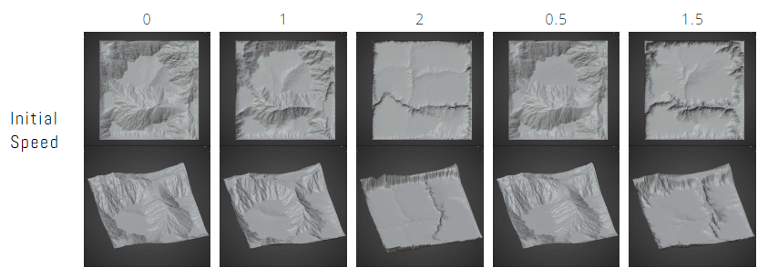
- Initial Speed
- Initial speed of each droplet
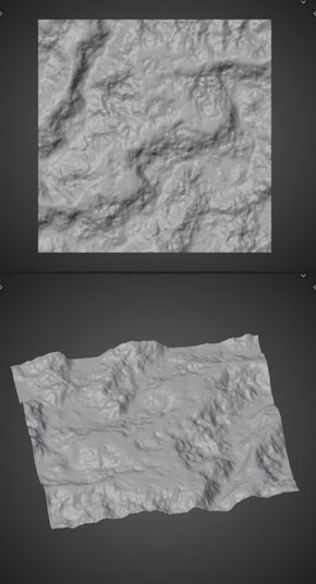
Example
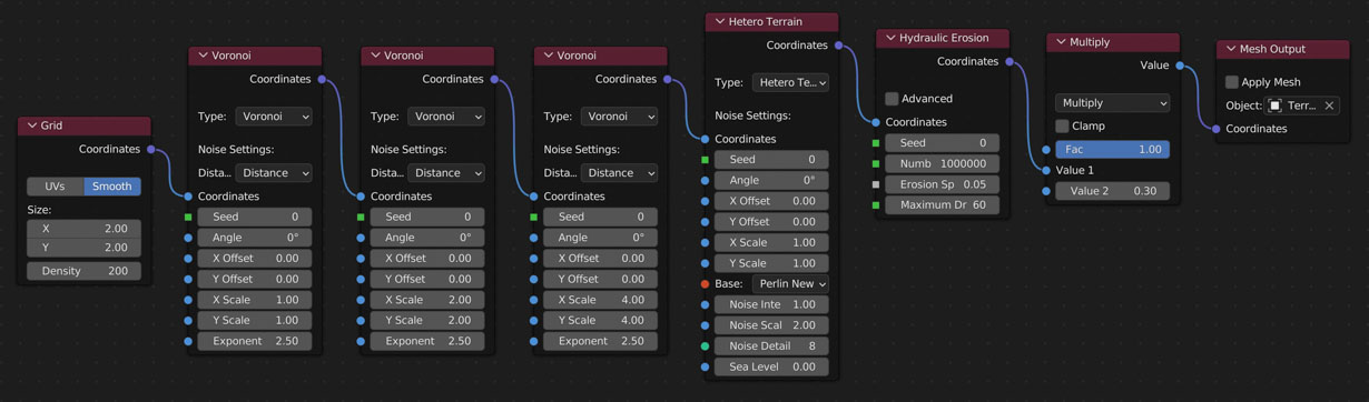
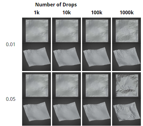
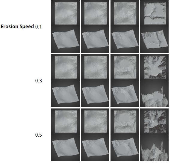
Understanding Erosion Settings
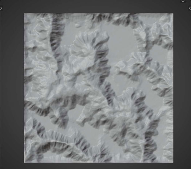
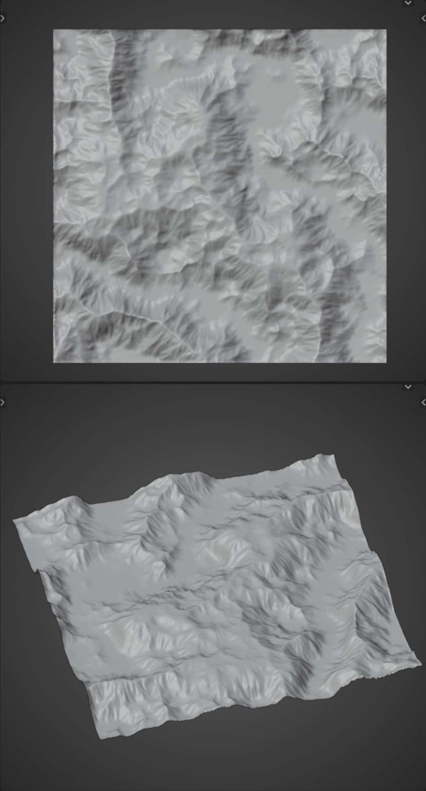
Erosion Speed vs Number of Drops
Default Settings used unless otherwise stated:
- Number of Drops: 100,000;
- Erosion Speed: 0.3;
- Max Lifetime: 60;
- Inertia: 0.5;
- Sediment Capacity Factor: 4;
- Minimum Sediment Capacity: 0.01;
- Deposit Speed: 0.3;
- Evaporation Speed: 0.01;
- Gravity: 4;
- Initial Water Volume: 1;
- Initial Speed: 1;

Placement of Math Nodes
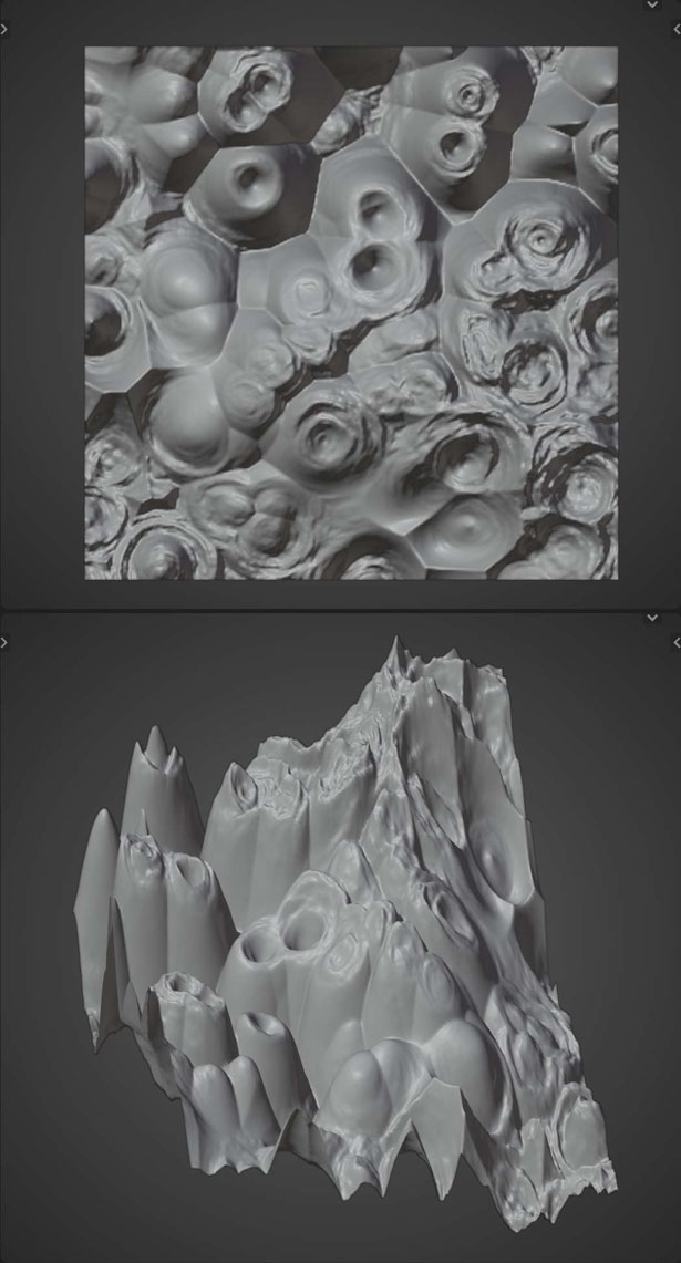
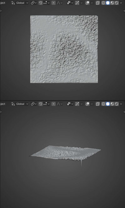
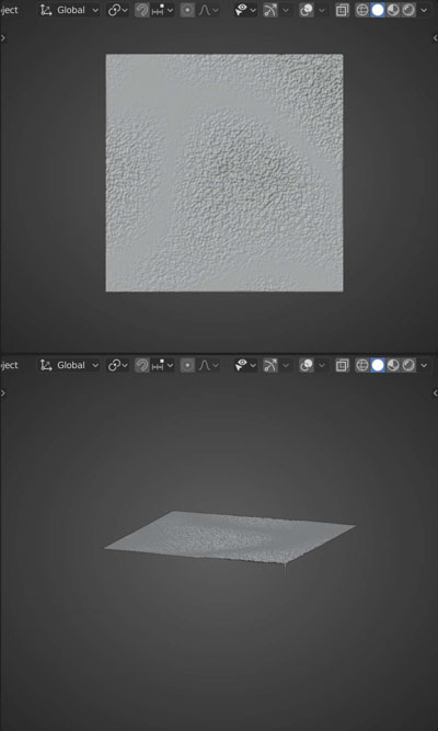
Shrinking the height of your plane often makes eroded meshes look more realistic. Here are examples of the differences when you place your multiply node (or other shortening node) before and after the erosion node:
Multiply Before:
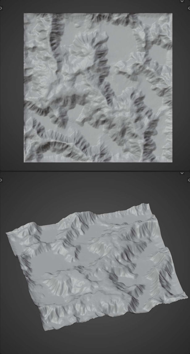
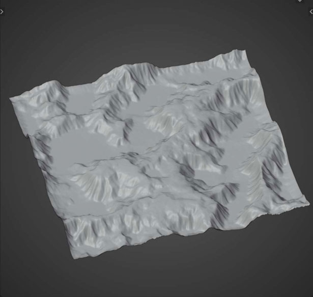
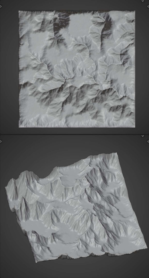
Multiply After:
Simulates the effects of rain on terrain.
- Randomize the location of all the rain drops. Is NOT consistent.
- Number of raindrops to simulate. Higher values increase simulation time
- Affects how much sediment to erode (remove) from terrain
- The maximum amount of time (iterations) the droplet has to complete its travel throughout the terrain. Higher values allow for more droplets to complete their paths, though the default value typically is enough. Higher values increase simulation time
- Inertia
- The amount of inertia each drop starts with. Smaller values result in deeper grooves
- Sediment Capacity Factor
- Maximum amount of sediment each droplet can carry at a given time. Higher the faster the droplet is going. When capacity is met, droplet deposits sediment (adds a bit to the terrain)
- Minimum Sediment Capacity
- Amount of sediment the droplet will always carry
- Deposit Speed
- Affects how much sediment to deposit (add) to terrain
- Evaporation Speed
- Affects the lifetime of the droplet. Higher values reduce lifetime quicker
- Gravity
- Affects the speed of the water droplet.
- Initial Water Volume
- Initial size of each droplet
- Initial Speed
- Initial speed of each droplet
Example
Understanding Erosion Settings
Erosion Speed vs Number of Drops
Default Settings used unless otherwise stated:
- Number of Drops: 100,000;
- Erosion Speed: 0.3;
- Max Lifetime: 60;
- Inertia: 0.5;
- Sediment Capacity Factor: 4;
- Minimum Sediment Capacity: 0.01;
- Deposit Speed: 0.3;
- Evaporation Speed: 0.01;
- Gravity: 4;
- Initial Water Volume: 1;
- Initial Speed: 1;
Placement of Math Nodes
Shrinking the height of your plane often makes eroded meshes look more realistic. Here are examples of the differences when you place your multiply node (or other shortening node) before and after the erosion node:
Multiply Before:
Multiply After:
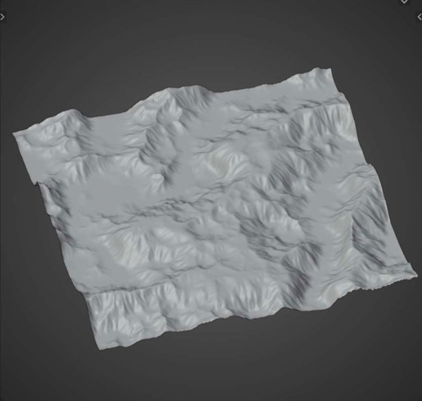
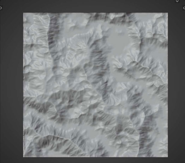
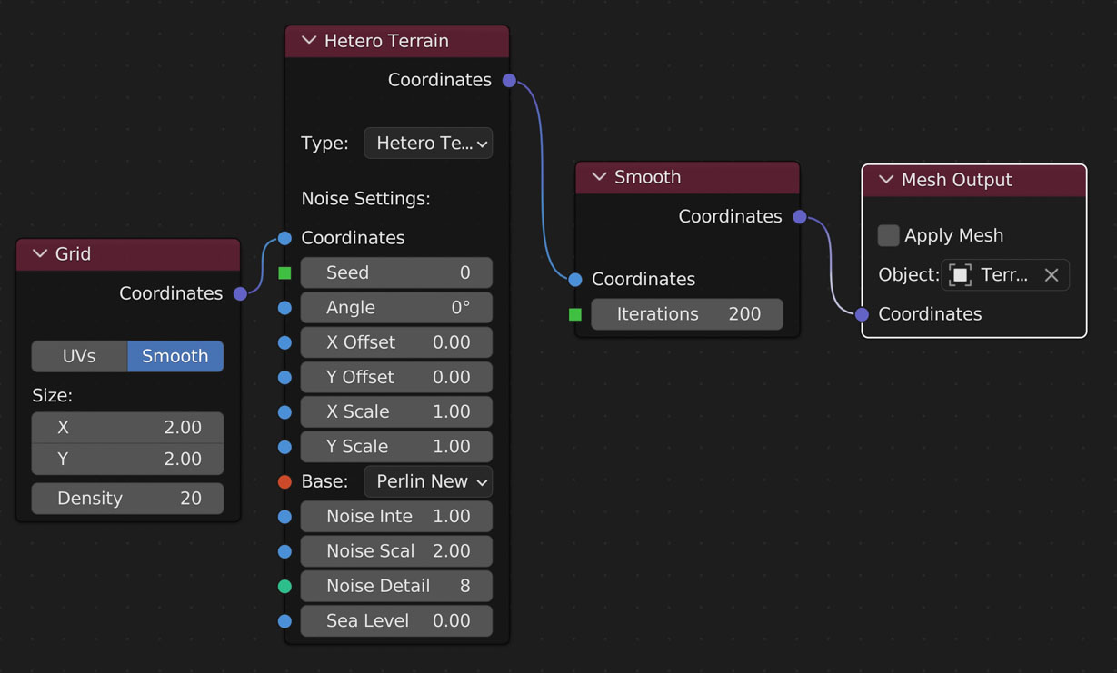
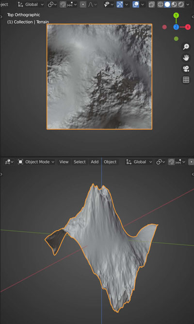
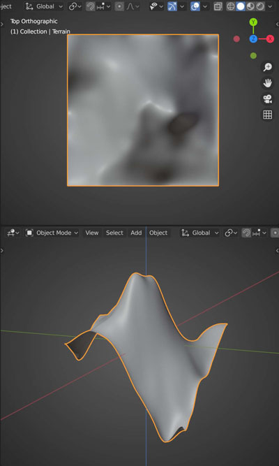
Smooth
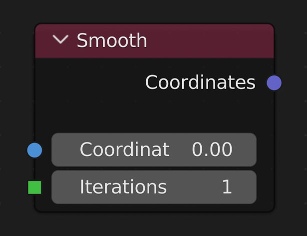
Average surrounding values for each Value once per Iteration
- Iterations
- The amount of times to go through and average the heights
Example

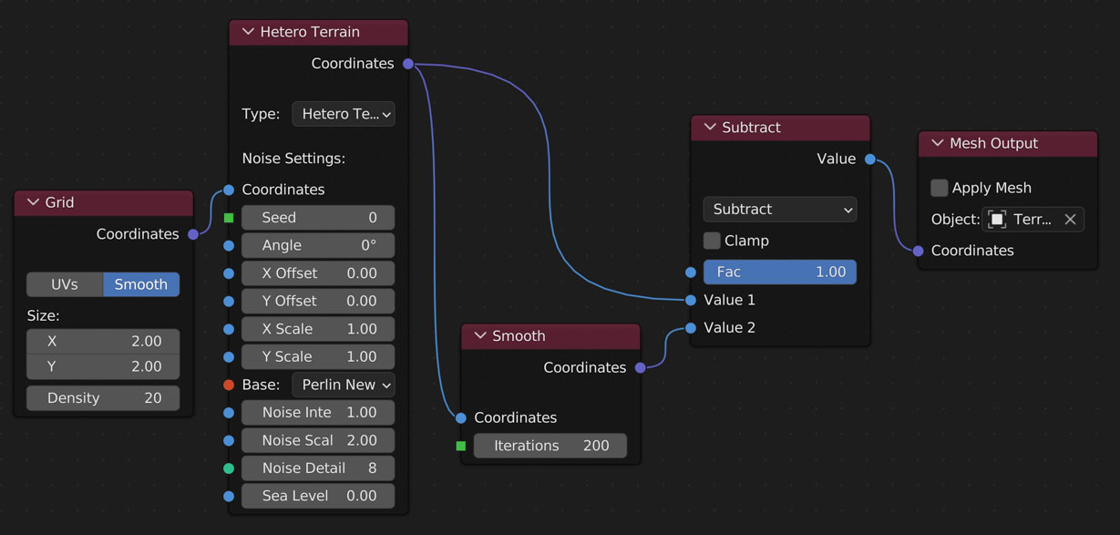
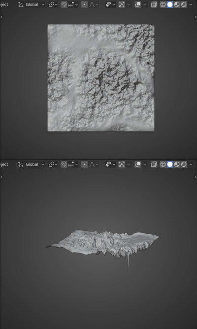
High Pass Filter
Grabbing just the details. You then can add the result to other geometry to add details you wouldn’t normally have
Average surrounding values for each Value once per Iteration
- Iterations
- The amount of times to go through and average the heights
Example
High Pass Filter
Grabbing just the details. You then can add the result to other geometry to add details you wouldn’t normally have
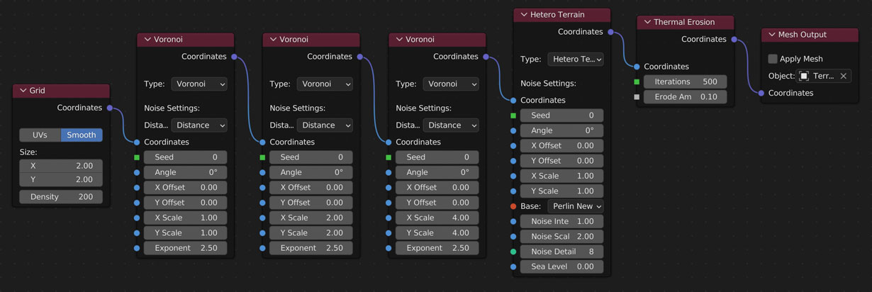
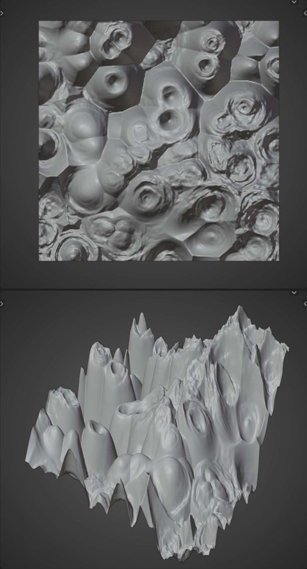
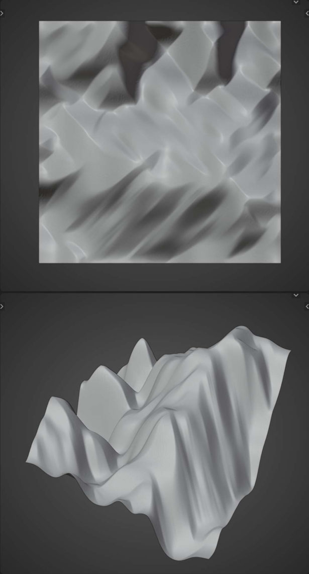
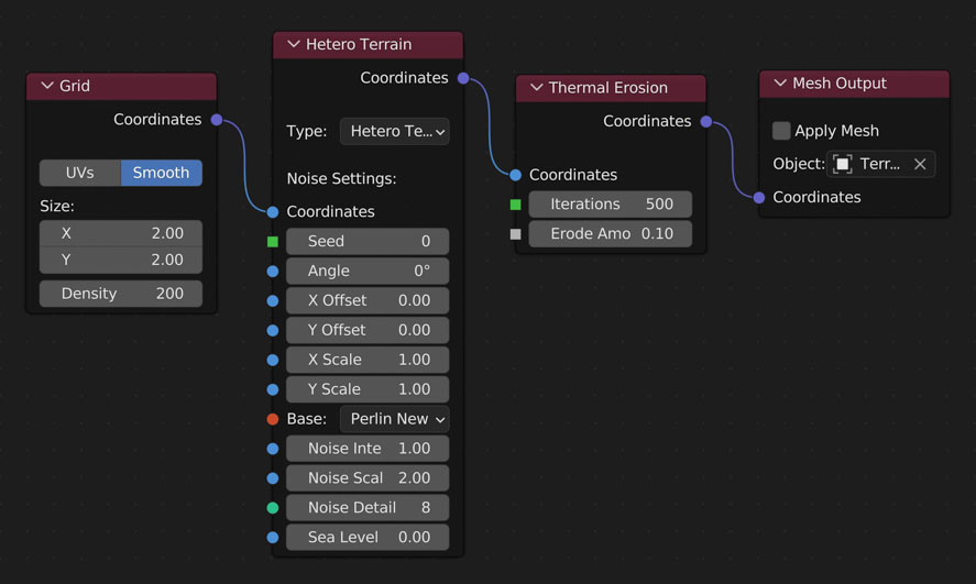
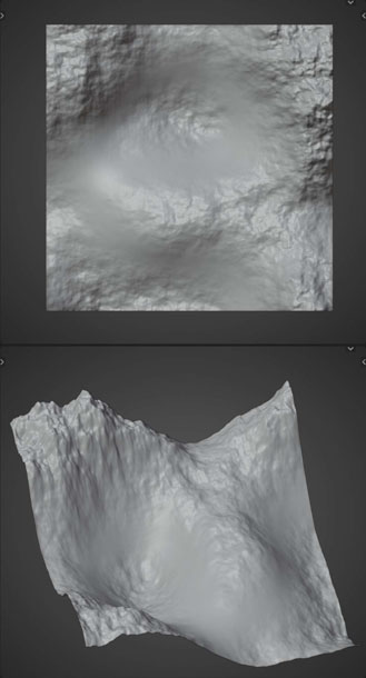
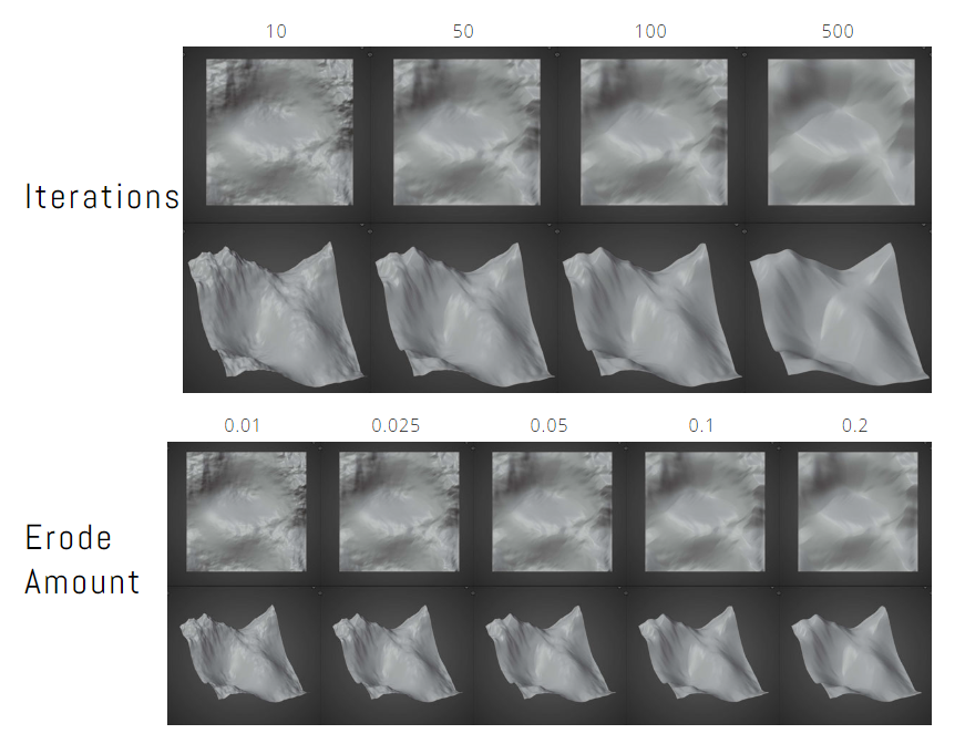
Thermal Erosion
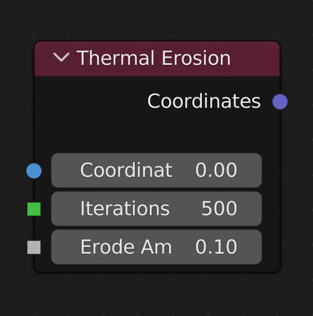
Simulates erosion of ice-bearing permafrost by the thermal action of moving water. Basically, this node goes through the surrounding vertices of each vertex and moves sediment from the current vertex to the lowest vertex.
- Thermal Erosion’s speed is dependent on the resolution of the plane and the number of iterations.
- Iterations
- Number of times to go through all vertices
- Erode Amount
- Amount to move from the current vertex to the lowest
Example
Understanding Erosion Settings